Wastegate
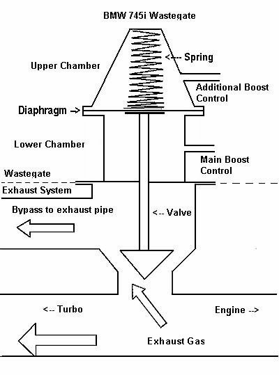
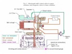
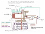
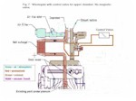
| The BMW 745i uses standard KKK K-27 turbo and an external wastegate with Motronic controlled magnetic valve. Boost pressure pushes against the diaphragm that is backed by the spring holding the wastegate shut. As boost rises, the diaphragm moves against the spring, gradually compressing it. | |
|
When this occurs, the wastegate is opened, bypassing exhaust gases
around the turbo and so controlling turbo speed and thus boost pressure.
An ECU-controlled solenoid valve regulates the boost pressure that is
fed to the wastegate's lower chamber. In order to tune a 745i engine to higher power levels one has to understand the basic operation of 1) The Wastegate 2) The Control mechanism and 3) The Protection mechanism. 1. Wastegate |
|
|
2. Exhaust gas pressure in the exhaust manifold Counter forces to those are: Summary of available boost ranges with standard 745i wastegate equipped
with added connector in the upper chamber: These are the practical limits without any adjustments covering power range from 250 hp to over 500 hp, which to most of us is quite sufficient. Later on in this document we will give you examples of different ways to adjust the power ranges either from the cockpit or from the engine compartment. |
|
| 2. Boost Control Mechanism | |
|
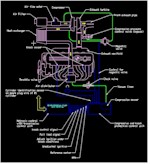
The wastegate is controlled by the Engine Management System, which includes Motronic Unit and Knock Sensor Unit. Those send signals to the magnetic valve, which in turn controls the amount of pressurized air fed to the lower chamber of the wastegate. Click the picture on the right hand side to see the whole system. The magnetic valve is quite "busy" all the time: |
|
|
* Otherwise it is constantly fine-tuning the air flow to keep the boost
at the same level. Note that the standard Motronic program will cut off fuel supply at approx. 0.7 bar (even in fast peaks), so you should always install the Chip Upgrade program before changing the boost levels. 3. Engine Protection Mechanism This function is important to understand when making changes to the boost levels and to the ways the boost levels are controlled. In some tuning configurations you will lose the automatic boost reduction function totally or partially and then you have to decide how to add alternative protection (like fuel/air mixture monitor) to your engine. |
|
|
Now you know how the system works so next step is to select suitable way to increase power. Here we will show you few examples how to do it starting from the simplest way. As power is simply a result of available fuel and air you should
do following basic checkups and installations in all cases: |
|
| Setup alternatives: | |
| 1. Standard wastegate with reduced air pressure to lower chamber | |
|
In this setup you reduce the airflow between the wastegate and the
magnetic valve in one of the three following ways: |
|
|
In both above cases you can install the valve in either the cockpit
or in engine compartment. Cockpit installation will cause some turbo
lag, but from our experience that is not so bad compared to the convenience
of real-time adjustment. One good alternative is electric motor valve
in engine room with just the control potentiometer in the cockpit. With these setups you can control power levels between 0.3 bar and
0.8 bar. Mid range boost will be close to 1 bar giving excellent passing
acceleration. |
|
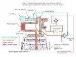
| The automatic boost reduction function in knock situations will work with 100% to 0% efficiency. For full 100% efficiency you need to install another magnetic valve (in parallel to the manual valve) which is controlled by a separate signal from the knock sensor electronics - Fig. 8 -. However, knock is not a major problem in these power levels and if you have installed a fuel/air mixture monitor you can set up a safe power level with that. Knock is a result of lean mixture. Note that the knock engine protection with ignition timing is always at present anyway. | |
| 2. Wastegate with additional air hose connector in the upper chamber | |
|
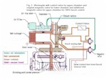
The possibility to control air pressure in the upper chamber gives
a number of possibilities to control the power and power range. Typical
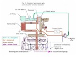
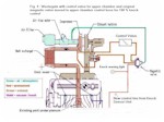
setup today is the following: The automatic boost reduction function in knock situations will only work in low power setup. For full 100% efficiency you need to install another magnetic valve - Fig. 3 - (in series with the manual valve) which is controlled by a inverted, separate signal from the knock sensor electronics. Knock will shut down the pressure to the upper chamber. Note that the knock engine protection with ignition timing is always at present. As in this setup the Motronic and Knock Sensor control to the magnetic
valve does not have much effect one could remove it completely - Fig.
4 - and apply constant boost to the lower chamber (it is needed
in order to reach the 0.3 bar low boost level). Then this magnetic valve
could be used in the upper chamber hose for knock shut down with a inverted,
separate signal from the knock sensor electronics. That signal could
also be used for a warning light installed e.g. in the instrument cluster. |
|
| 3. Combination of Alternatives 1 and 2 | |
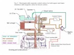
| The widest power range and highest boost can be achieved by combining the best parts of alternatives 1 and 2 - Fig. 5 - .: | |
|
* Adjustable valve for upper chamber section (for high boost limit
between 0.8 and +1.6 bar) Note that if you just use the adjustable valve for the upper chamber section and leave the lower chamber to atmosphere level you will have a boost range from 0.7-0.8 bar to +1.6 bar. The adjustable valve for lower chamber is needed to get the minimum boost down to 0.3 bar ( if you need it!). Ideally, the two separate adjustable valves could be replaced by one splitting valve (if available) - Fig. 6 -. Like said earlier, electric motor valves can be used also for easy cockpit control. Also fully electronic boost control units are available from several companies. |
|
| Finally, as some people do not care too much of the possibility to automatically lower the boost in knock situations here is example of their typical setup - Fig. 7- . They either rely on their ears or use fuel/air mixture analyzers to set up the power levels. The use of a rising rate fuel regulator is also a safety factor. Remember that max. usable power may vary daily depending on ambient conditions (temperature, humidity, altitude). | |
Special note: The new electronic control line from Knock
Sensor Unit for full knock protection must be installed.
That requires soldering
one wire inside the box. We may introduce a small "black box",
which includes the extra
magnetic valve, control electronics, input from
the knock sensor box and output for the knock warning light.
For the time
being you can build your own. Go to the "Knock Box" section here to get some
guidelines how to do it.
| Examples of available accessories: |
Link or picture
|
| 1. Modified wastegate with control valve and hoses is available from Team745. This is a complete kit including boost control port in upper chamber and additional mechanical adjustment for spring tension. | |
| 2. Universal Boostvalve Kit from Boostvalve is available at $39. | |
| 3. Super-Duty Boost Controller Kit from www.dawesdevices.com is available at $35 or at $50 | |
| 4. These valves were sourced from the German company IMI Norgren Pty Ltd - branches in most states and countries. The parts that were used were:· 1 x R07-200-RNKG Inline 07 ¼ Regulator Relieving 7Bar;· 1 x V07-200-NNKG Inline 07 ¼ Relief Valve 7 Bar;· 2 x 2069-02 07 Spring 0.7 Bar (brown);plus mounting brackets and four ¼-inch barbed hose fittings to suit the regulator and relief valve. The total cost was A$83 (including GST).Note that the pressure reg and relief valve are nominally 7 Bar (ie are designed to set pressures up to ~100 psi), and so you need to buy the softer springs (rated at 0.7 Bar - 10 psi) to go inside each of them. The bodies easily unscrew and spring replacement takes only a few moments. If you are going to be running very high boost, retain the higher rated springs as well - for 1 Bar (14.5 psi) boost, the softer springs worked fine, despite their nominal 10 psi setting (select spring values based on your desired max. boost level). | |
| 5. Road///Race Engineering sells in internet a number of different boost control valves from simple cockpit control valves to fully electronic boost control systems. | Road///Race Engineering |
| 6. Your local hardware stores are good sources for different kind of pneumatic valves | |
| 7. Your local car tuning companies can be your best source for all the accessories you need to setup your 745i boost control. |
